


Time:Nov 03,2026
By:Bailu
The pressure test on the die-cast housing leaks at the same spot on every sample, and the casting shop blames the alloy while the buyer blames the machine. More often, both are missing the real cause: a thick hotspot in the part geometry that no machine setting can feed properly. Porosity in die casting is designed in before it is cast. It comes from walls that vary too much, ribs that act like heat sinks, gates that choke the feeding path and overflow wells placed where the metal rarely reaches. This article walks through the structural design choices that remove porosity at the source.

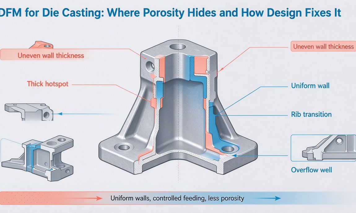
Shrinkage porosity opens where the metal solidifies from the outside in, leaving a cavity in the last-to-freeze thick section. Gas porosity comes from air, vapor and lubricant trapped inside the die, which bubbles out as the metal front collapses around it. They look different under magnification and they are fixed by different levers. Shrinkage responds to wall thickness control and feeding direction. Gas porosity responds to venting, gate position and slower, controlled fill. A DFM review should name which defect your part is likely to develop, because redesigning the walls does nothing if the real problem is a poorly vented cavity.
Uniform wall is the single most effective porosity control. When one section is 3 mm and the boss next to it is 10 mm, the thin wall freezes first and seals off the feeding path to the thick section, which then shrinks into a cavity. The fix is not to make the thin wall thicker everywhere but to thin down the thick region: core out the boss, switch to a hollow boss with a core pin, or split the thick section into ribs. As a rule of thumb, keep wall variation under about 25 percent between adjacent sections, and let walls taper gradually rather than step. Bailu's DFM reports mark every hotspot on the CAD model, so the design changes are visible before the mold is machined.
Ribs are where over-engineering shows up. A rib that merges into the wall at a sharp corner creates a local hotspot three times the wall thickness, and that hotspot is the spot that bleeds in the pressure test. The fixes are standard: keep rib thickness at 50 to 70 percent of the wall it grows from, blend the junction with a generous radius, and drill or core out bosses instead of stacking solid cylinders onto the wall. Bosses that need to carry screws should be designed as hollow features from the start, with the tap depth set so the cast material around the thread stays thin and free-flowing. Compared with a supplier that quotes the CAD as drawn, a die casting manufacturer China buyers rely on pushes back on every rib that breaks the ratio.
The gate decides where the metal enters and which way the front travels. A good gate feeds the thick sections last, so solidification follows a path from the far end back toward the gate, the opposite of injection molding logic. Overflow wells at the end of the flow path collect the cold front and trapped air, and they should sit where the metal arrives last, not symmetrically for neatness. Venting along the parting line and over slides gives trapped gas an exit; cavities with deep ribs often need ejector-pin venting at the far end. When the gate lands wrong, the part shows gas bubbles in the last-filled region regardless of how uniform the walls are, which is why gate position is reviewed together with the wall map in the same DFM session.
Small geometry details quietly feed porosity. Sharp internal corners act like risers, concentrating hot metal; radiused corners let the flow spread and freeze evenly. Draft angles that are too shallow drag the metal against the die, slowing the local fill and trapping gas. Deep, narrow ribs with tight corners are notoriously hard to vent, and they should be opened up or split into parallel ribs. Ejector pin placement also doubles as venting, so the DFM review should place pins at gas-trap locations rather than only where the part needs pushing out. On assemblies that mix cast nodes with sheet metal fabrication, these cast features are the interfaces that later bolt up, so their dimensional density matters as much as their porosity.
High-pressure aluminum die casting already holds porosity to low levels on well-designed parts, but the target depends on the requirement. Non-cosmetic structural parts can tolerate slight subsurface porosity hidden by shot blasting. Parts that will be machined, plated or anodized need a denser skin, because machining opens pores and finishing treatments expose them. Pressure-tight housings are the strictest case: they may require vacuum-assisted casting or infiltrated porosity treatment, and the design changes above are what keep those processes affordable rather than experimental. Bailu Tech sets the porosity target against the part's function during DFM, so the tooling is specified for the tolerance the product actually needs.

Run this list on the CAD before the mold order: wall thickness map with every hotspot circled, rib-to-wall ratios checked at each junction, bosses cored out, radii at all internal corners, gate position chosen to feed thick sections last, overflow wells placed at the final fill points, and venting arranged along the parting line and over pins. Ask your caster for a solidification comment on the design, and ask whether they will run a fill simulation before steel is cut. Ask also how the gate and overflow changes are recorded in the die casting processing file for the mold, because a documented process is what keeps the same results on a repeat order. Huzhou Bailu Technology treats that simulation as a normal DFM deliverable, because the cost of one simulation run is a fraction of the cost of relocating a gate after the mold has been hardened.
Let us brighten your life with safety, efficiency,and expert craftsmanship.
Contact Us
Phone : +86-159 0682 2387
WhatsApp/Wechat: +86-159 0682 2387
Email : info@bailusolution.com
Copyright © 2026 Huzhou Bailu Technology Co., Ltd. All Rights Reserved. Design by BONTOP.